


 Steve Neemeh
LHP and Konrad Partner to Deliver New A³DAS Solution - 8 Takeaways
SME Interview Series: LHP and Konrad Technologies Partner on A³DAS Solution LHP’s Vice President of Marketing, Marty Muse, sat down with Steve...
ADAS Testing for Robust Verification & Validation Process
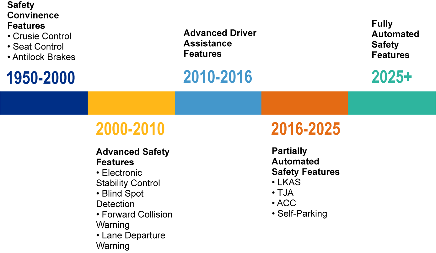
Advanced Driver Assistance Systems (ADAS) have become integral features for automobiles on the road. Their inclusion was not just to reduce driver stress but also to promote safety. Existing ADAS features such as adaptive cruise control, lane-keep assist, collision mitigation braking system, and many more have proven results that suggest their inclusion has significantly reduced head-on, rear-end, and cross-traffic collisions. The fast-paced advancement of ADAS features requires an ADAS testing solution.
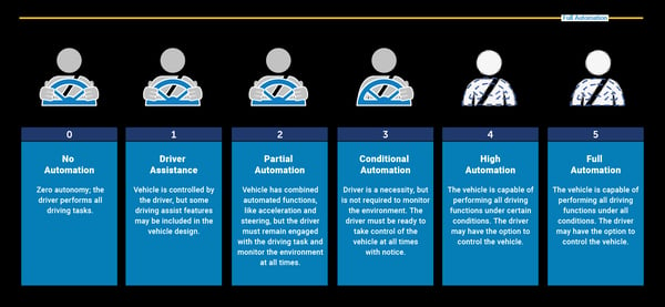
Depending on the level of autonomy, ADAS features vary in their functionality. As per SAE, Level 0 is where a driver has full control of the vehicle, and Level 5 is where the vehicle can perform driving functions under all driving conditions. In the current scenario, most of the ADAS features fall within L0-L2 autonomy, which still requires the driver to take control, even in the presence of combined automated controls. The development of ADAS features, as described by NHTSA, is shown in Figure 3. These features are heavily present in new production vehicles as they have been shown to aid in fostering a safe driving environment. Original Equipment Manufacturers (OEMs) must be even more careful due to the user’s reliance on these technologies to perform and aid some driving-related functions. As a result, OEMs should instill a safety-by-design approach through which any shortcomings associated with sensor technology that could lead to hazards can be evaluated during the early design phase.
Some OEMs follow best practices through standards such as ISO 26262, which covers Electronic/Electric (E/E) safety-critical malfunctions associated with a system. Understanding system behavior and evaluating hazards are two crucial aspects that contribute to safe system design. To ensure these factors are evaluated for any E/E system, for L0-L2, ISO 26262 suggests a strategic framework starting from the design phase through testing and verification & validation (V&V). This process should be deeply rooted within an organization during the early design phase to help understand any potential risks beforehand, as it can impact system confidence. Due to the dynamic behavior associated with L3-L5, it is difficult to address these aspects during the early design. The rigor provided by ISO 26262, along with a strategic framework, was proven to be effective if implemented from the design phase to testing to the early production phase for any Automotive Safety Integrity Level (ASIL) yielded item.
For both current and legacy systems under development, engineers rely on test strategy and V&V criteria. The testing schema proposed by ISO 26262 satisfies the testing requirements to verify and validate L0-L2 and partially L3 systems since its faults were already known. However, the ISO 26262 V&V process falls short when testing L3-L5 systems. The vehicle operates in varying environmental conditions. Such a change in the landscape can introduce new risks during operation, where not all testing scenarios can evaluate the unknown risks associated. It is challenging for OEMs to develop a robust V&V process to make their systems fail-safe and comply with safety-by-design criteria.
Due to the residual behavior of risks involved in unknown hazards, it is challenging for engineers to test for any of these using the current simulation techniques. ISO PAS 21448: Safety of the Intended Functionality (SOTIF) has a theoretical approach and set of guidelines to help engineers understand system behavior for corner case scenarios, scenarios that do not show up during testing.
ISO 26262 is robust enough to identify E/E failures for autonomy L0-L2. What is the case for autonomy L3-L5, where unknown system hazards are more prevalent? ISO 26262, along with ISO PAS 21448, helps to identify and promote risk-free approaches for all levels of autonomy.
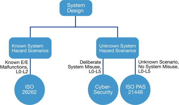
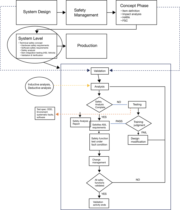
Figure 2 System design with known/unknown hazard scenarios and corresponding safety standard
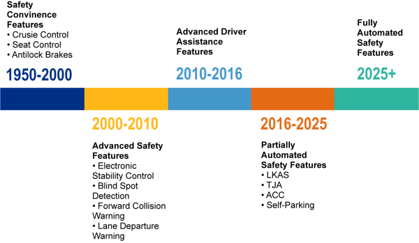
Figure 3: Safety features by NHTSA
V&V Strategy ISO 26262/ISO PAS 21448
ISO 26262 Process Overview:
The ISO 26262 process starts by providing guidelines for promoting a safety culture by defining the management of functional safety. In the next steps, the item is defined through the concept phase, in which all the possible hazards associated with the system are evaluated. This helps in calculating the ASIL rank. Further, a safety goal is derived based on the ASIL-ranked hazards, which are essential for providing and generating requirements. In ISO terminology, all the requirements will be derived under the Functional Safety Concept (FSC), and they form the basis for lower-level system requirements. FSC is critical for developing a safe system design and helps to develop requirements defined in the Technical Safety Concept (TSC). This forms the basis for hardware and software safety requirements. Through the safety analysis approach, the residual risks associated can be further evaluated. In the following sections, a detailed testing and V&V strategy will be discussed.
Validation and Verification:
Validation is used to ensure that a system is free from any unreasonable risks due to unknown hazards. Generally, in the V&V process, the hazards and risks that were not evaluated during the initial hazard and risk analysis can be evaluated using a safety-analysis approach – Failure Mode and Effect Analysis (FMEA) or Fault Tree Analysis (FTA). To satisfy the validation coverage criteria, simulations help to explore a wide range of possible relevant scenarios. Through this process, the ASIL rank allocated to the system can be even more robust, which helps in implementing an appropriate testing strategy applicable to L0-L2 systems.
On the contrary, when the vehicle takes control, for L3-L5, there is a high possibility of mode confusion and system responsibilities. These risks cannot be tested during V&V. To address the shortcomings of dynamic risks associated with the system, ISO PAS 21448, draft, is setting V&V guidelines. However, ISO PAS 21448 must address the following questions to establish a robust V&V process.
The following sections introduce the V&V scope, which includes verifying system requirements, leveraging the V&V process to increase system confidence, and system observation. These sections will also further address challenges associated with L3-L5 due to corner scenarios. The testing approach for defining testing goals, testing use cases, test targets, etc., which are clearly defined by 5 Who’s and 2 How’s 5W-2H approach that can be taken to overcome challenges posed by V&V, will be discussed as well.
The scope of V&V demonstrated in this section addresses advanced autonomy levels – L3-L5. The validation process is critical for safe feature deployment, especially in the cases of L3-L5 autonomy. For L0-L2 autonomous features, testing and validation strategies provided by ISO 26262 are enough to validate the system design. But in cases where system misuse is deliberate, SAE J31408/ISO 21434 (under development) standards suggest guidelines for security-related issues.
Testing alone cannot achieve complete system validation, but it can be achieved by robustly implementing quality audits, expert reviews, or safety analysis techniques. The validation plan schematic shown above illustrates how it can be implemented using the ISO 26262 standard. With increased complexity, testing helps to determine any hidden faults and increases the system's confidence for use in real-time driving conditions. The following steps map out the required criteria that the V&V process must satisfy.
STEP 1: Requirements Verification to Satisfy System DesignWith the help of readily available and known scenarios, engineers can further ensure system safety through testing. The verification process mainly focuses on testable requirements and can rely on safety by design processes that have long been used in production vehicles. The concept of safety by design is fundamental, but for autonomous vehicles, it can be difficult due to unknown scenarios that cannot be directly verifiable. For example, scenarios such as brightness, construction zones, and tunnels can occlude the sensors and create an unsafe driving environment. To address these issues, validation of both known and unknown scenarios is necessary.
STEP 2: Leverage Validation Process to Maximize System ConfidenceIn real-time conditions, a system with 100-percent reliability and 0-percent free of fault is difficult to achieve due to uncertainties that cannot be avoided. Factors such as the Operational Design Domain (ODD) and the Object and Event Detection Response (OEDR) are crucial to ensure system functions are within the design domain and the user’s required response. Typically, validation is accompanied by testing the verified system either by controlled on-road testing (e.g., proving grounds) or through simulations such as Hardware in the Loop (HIL), Software in the Loop (SIL), and Driver in the Loop (DIL). During validation, the system’s function is to be stable to avoid any unknown scenarios.
STEP 3: Post Deployment Observation.
Post-deployment observation is an important step that enables safety engineers to introduce and update any changes required to the system functions. The changes or updates can result from long-term tests, field monitoring, or security tests. Safety engineers need to ensure that introducing changes and updates does not introduce any new risks or alter the system functions, which can impact safety.
It is highly challenging to test all the scenarios for any system, as some sensors can present challenges due to their dynamic nature and uncertainty. A positive balance between detecting all the known and unknown scenarios and system performance is necessary. These are the five challenges presented in this paper (as adapted from Intel Safety First for Automated Driving).
Challenge 1: System Safety without Driver InteractionFor L0-L2 automated vehicles, since the vehicle is constantly under driver control, all the worst-case scenarios can be accounted for to ensure system safety. But in L3-L5, the vehicle is in control, and the driver does not need to be fully alert. Safe system operation requires a unique approach with the highest rigor, which allows the vehicle to drive by itself. Statistical validation methods, such as regression analysis and standard deviation, can be applied to the obtained data sets through testing.
Challenge 2: System Safety with Driver InteractionComplex maneuvers such as overtaking, lane changing, and tunnel driving can be challenging tasks for autonomous vehicles. As part of the V&V process for L3-L5, all these complex maneuver tasks need to be assessed. This list can increase once autonomous vehicles mature. Mode transitions, autonomous to human, for complex scenarios require the user to be available to constantly monitor system performance and take control if any system anomalies are found. Also, long-term autonomous driving makes the user complacent, and it is a safe practice to include these scenarios in the V&V process and system impact analysis.
Challenge 3: Scenarios Not Known in TrafficSensor interaction is a normative procedure for L3-L5 to perform critical driving tasks. It is important that sensors capture all the essential information and respond instantaneously to generate the necessary vehicle control functions' actuation. Driving patterns are always shifting, and autonomous vehicles should be able to adapt to these unknowns. Security-related risks in traffic also arise when the Vehicle-to-Vehicle, Vehicle-to-Pedestrian, etc. (V2X) interactions are in full implementation. All these factors are inputs into validation.
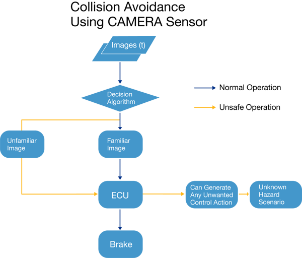
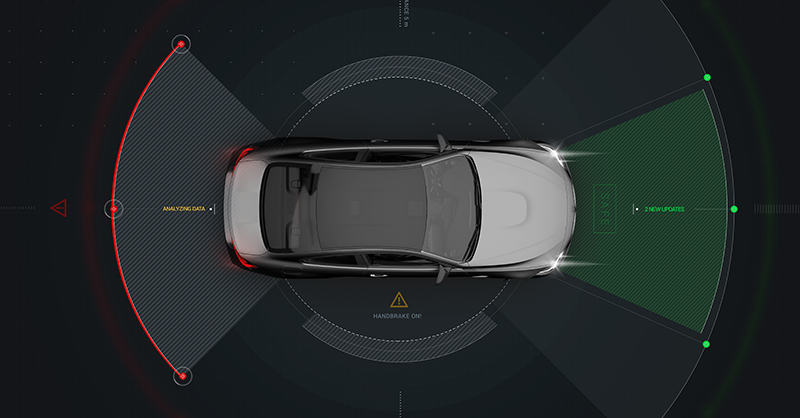
Figure 4 is an example of a simplified illustration of normal/unsafe operating conditions for a collision-avoidance system equipped with a camera sensor. In this scenario, the camera sensor relays information in the form of images at the current time (t) to perform a driving brake operation. The decision algorithm helps to classify images based on a familiarity index, which includes preloaded route geography, environmental conditions, speed range, and other factors. In a normal operation case, where the image is identified as familiar, the ECU can send signals for brake actuation. For images that cannot be identified as known, the ECU might generate unwanted driving control action, which can lead to a hazard.
|
Function |
Collision Avoidance Using Camera Sensor |
|
System Composition |
Input: Images (t) – Images at the current time, t
Processing: Decision Algorithm – Provides a decision on image classification based on the familiarity index
Processing/Actuation Initiation: ECU – Processes the information and arms the appropriate driving control function
|
|
Scenario |
An L4 system trying to maneuver from point A to point B is performing a driving control action based on the received images from the camera sensor |
|
Possible result |
Normal Operation – The System safely brakes the vehicle based on the identified images
Unsafe Operation – Dynamic environmental conditions resulting in decision confusion and unwanted control generation leading to a hazard |
Challenge 4: Validation of various system configurations and variants.
ADAS features require software updates or hardware changes during autonomous vehicle lifetimes. Due to the complex nature of ADAS system configurations for L3-L5, it is critical to address how the updates and modifications to the system are handled during their service time in the V&V process.
Challenge 5: Validation of systems/subsystems based on machine learning.
Algorithm complexity in L2 features is less than in L3-L5. Since L3-L5 autonomous vehicles rely heavily on complex algorithms that include extensive machine learning or artificial intelligence, V&V efforts require a different approach. Implementing validation for subsystems within a system configuration can be challenging, which increases testing effort.
Testing is a key requirement for V&V to ensure proper design implementation. Testing within validation also helps to verify whether the specified functional requirements are met. For L3-L5, validating autonomous driving features cannot be completely achieved by the current test criteria proposed by the functional safety standard and the safety of the intended functionality.
Establishing a robust test strategy is critical for the testing process. To understand crucial elements that contribute towards testing strategy, 5W-2H (Ohno, 1998; Tague, 2005), elaborated as 5W: Who?, What?, Where?, When?, Why?, and 2H: How?, How well? needed to be understood. For L0-L2, the when and who questions can be answered by the current process development standards. Validating a system design alongside answering the remaining questions, excluding those for L0-L2, by the 5W-2H concepts can improve the overall V&V process and is defined in Table 1.
|
WHY? and HOW WELL? |
Test goals, completion criteria, metrics |
|
HOW? |
Test techniques |
|
WHERE? |
Test platforms |
|
WHAT? |
Test elements or objects under test |
Table 1: 5W-2H Concept explaining the Testing Strategy
These factors help in establishing a refined testing process for L3-L5 autonomous driving to support validation.

Risk identification and hazard evaluation as early as the design phase is critical, as it can impact the system's integrity. Overall, safer systems help promote safer roads. A systematic safety approach can be possible through an integrated ISO 26262 process implementation. Increased user demand for ADAS features in automobiles requires OEMs to tackle new challenges and comply with regulatory requirements. Due to the system complexity associated with ADAS sensors, a unique safety approach rather than a traditional process is required.
The operation lifecycle for ADAS sensors is mostly in a dynamic environment; testing is required to ensure system safety. Testing and V&V processes play an important role as they provide visibility on the system's intended functionality, system failure modes, behavior, and safety mechanisms' robustness. SOTIF suggests the same procedure for V&V of unknown system behavior for corner case scenarios, which is common with higher autonomy levels.
For several years, LHP has helped customers with the ISO 26262 process, work product development, and functional safety assessments. With our expertise in ADAS and process development standards such as ISO 26262, ISO PAS 21448, Cybersecurity, AUTOSAR, and ALM tools, LHP can play a crucial role in an organization’s technical and process implementation needs.
|
Term |
Definition |
|
Corner Case |
Scenarios that are dynamic, and there is no visibility to them during the standard process implementation |
|
Scenario |
Description of a temporal development between several scenes in a sequence of scenes influenced by actions and events |
|
Safety by Design |
Detecting and minimizing risks as early as the design phase of any system/item/component |
|
ODD |
The specific condition under which a given driving automation system is designed to function |
|
OEDR |
The dynamic driving task includes monitoring the driving environment and executing an appropriate response to objects and events |
|
Levels of Autonomy |
Level 0 (L0) – Driver is in full control, no automation Level 1 (L1) – Driver is in full control, some driver assistance features included in vehicle design Level 2 (L2) – Partial automation with combined automated functions (e.g., steering, braking, etc.), the driver must be engaged at all times and monitor the environment Level 3 (L3) – Conditional automation; driver is necessary but not required to monitor the environment Level 4 (L4) – High automation; vehicle has the capability to perform certain functions Level 5 (L5) – Full automation; the vehicle can perform all driving functions |

SME Interview Series: LHP and Konrad Technologies Partner on A³DAS Solution LHP’s Vice President of Marketing, Marty Muse, sat down with Steve...
Improving driving safety through the reduction in opportunities for human error has been a focus of automotive manufacturers since the 1970s when...

In the ever-evolving landscape of automotive technology, researchers and engineers are at the forefront of developing and refining the most...
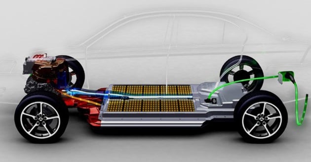
When Toyota launched the first Prius in 1997, many consumers probably didn’t imagine that just 20 short years later the electric- and hybrid-vehicle...
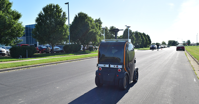
By partnering with PerceptIn’s modular approach to autonomous sensor development, LHP’s knowledge of embedded controls and system integration proves...