


 Adam Jungkunz, Ph.D.
Testing Requirements of Autonomous Features with National Instruments Powertrain Control Modules
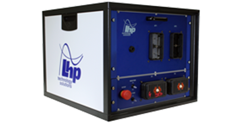
NI Drivven Powertrain Modules, Exclusively sold by LHPTS, an LHP division.
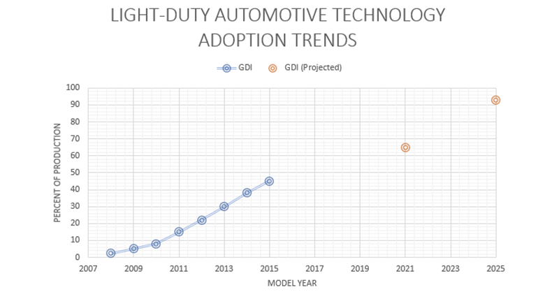
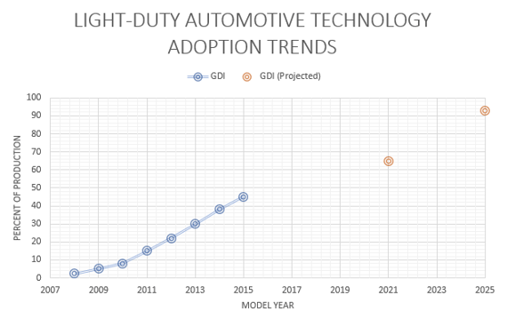
As automobiles continue to become cleaner, higher performing, and more reliable, their designs evolve. One critical system undergoing dramatic change is the fuel system; according to US EPA predictions, DI fuel systems in light-duty vehicles have been growing and are expected to grow to over 90% of the share of vehicles sold by 2025. As researchers and developers continue to innovate and look for engine solutions, understanding how to control these fuel systems is of the utmost importance.
GDI Fuel System Components
A typical gasoline direct injection system consists of several components: fuel injectors, a fuel rail, a rail pressure sensor, a medium-pressure fuel pump, and cam and crank position sensors. The components serve distinct functions: the pump pressurizes the fuel from about 3-4 bar (40-60 psi) to between 100-300 bar (1500-4500 psi). The fuel injectors spray the fuel directly into the cylinders. The fuel rail delivers fuel from the pump to the injectors, and the rail pressure sensor measures the pressure in the rail and sends a signal back to the engine control unit (ECU) indicating the current pressure in the rail.

The medium-pressure pump is typically cam driven as can be seen in this video. The cam lobe pressurizes the fuel, and a fuel quantity valve on the pump is opened and closed that allows the fuel into the rail. The timing of valve closing is critically important to building pressure in the fuel rail because the fuel is only pressurized while the cam has lifted the plunger.
Having the proper electrical interface to all these components is a key element to controlling fuel-rail pressure. If you don’t have an ECU designed to interface to all of them, or you are looking for an open-source ECU solution that allows you greater flexibility in controlling the engine, you need to have the right electronics to drive the injectors and read the sensors. To drive the injectors, you will need a half-H bridge circuit to send commands to the injectors. The injector needles are opened either by solenoids or piezoelectric stacks and thus need to be driven with appropriate hardware. Similarly, the valve in the fuel pump is driven by a solenoid and needs to be driven by a similar circuit. The pressure sensor typically sends out an analog voltage and needs to be read by an analog-to-digital converter, while the cam-position and crank-position sensors need to be read by either digital input channels or variable reluctance input channels, depending upon sensor type. LHP Technology Solutions, as a National Instruments (NI) Alliance Partner, specializes in selling, servicing, and supporting NI solutions for controlling direct fuel injectors, direct injection fuel pumps, and other internal combustion (IC) engine electronics.

To control fuel pressure, simply having the proper electrical hardware isn’t enough; the ECU needs a control algorithm to integrate the measurements and actuators together to achieve the desired fuel rail pressure. The approach taken in this article is PID (proportional, integral, derivative) feedback control law to determine the pulse width of the fuel quantity valve pulses based on measured fuel rail pressure. If the pressure in the rail is above the target value, the pulse width command to the fuel quantity valve will decrease to reduce the amount of fuel allowed into the rail. Since the injectors are running and spraying fuel into the cylinders to drive the engine, the pressure in the rail will decrease. Conversely, if the pressure in the rail is below the target value, the pulse width command to the fuel quantity valve will increase to increase the amount of fuel allowed into the rail, and the pressure will rise. Tuning proportional, integral, and derivative gains will yield better responses to changes in desired rail pressure or engine speed. Typical pulse values fall into the range of approximately 3-10 milliseconds.
To find the number of pulses to the command to the valve, take one of three approaches. First, try to do some research on the pump and the engine to find what number of pulses to command. Second, if possible, inspect the cam and pump to determine how many pulses (1, 2, 3, or 4, typically) to send to the valve. Look for cam lobes that drive the pump and count them. Finally, if neither of those methods is viable, pick a value and begin trying to determine the timing of the pulses.
To determine the timing of the fuel quantity valve pulses, sweep the commands throughout the range of operation as the engine is motoring and watch the fuel pressure. It should increase when you find the correct timing. If you picked a value of pulses and saw no increase in fuel pressure, try adding additional pulses to the system.
Additionally, in engines with variable cam timing, the timing of the fuel quantity valve pulses must be adjusted to compensate for the cam timing changes because the cam lobe for the fuel pump is moving along with the lobes for the intake and/or exhaust valves. This can be accomplished simply by adding the cam advance or retard adjusting cam position to the pulse timing to ensure the pulses driving the fuel quantity valve to continue to add pressurized fuel to the rail.
Now that you have all the information necessary to control rail pressure in a GDI fuel system, have fun!
Need more information? Download the latest white paper -Thermal Management for Electric Vehicle and Hybrid Electric Vehicle Systems - to learn more.
NI Drivven Powertrain Modules, Exclusively sold by LHPTS, an LHP division.
When Toyota launched the first Prius in 1997, many consumers probably didn’t imagine that just 20 short years later the electric- and hybrid-vehicle...
Today, automotive researchers and engineers are constantly evolving their research to optimize propulsion system control technologies for the...

What is Electric Vehicle Functional Safety Testing? Electric vehicle (EV) technology is evolving rapidly. Additionally, the demand for these vehicles...
LHP is releasing a new product into our model-based design and test workflow at the Automotive Testing Expo in Novi, MI on 10/20. The LHP...
Will Autonomous and Electric Vehicles Kill the Fuel Industry? Did you know the first electric vehicle was introduced more than 100 years ago? Today,...